#CH341 DRIVER DOWNLOAD DRIVER#
CH341PAR_LINUX.ZIP – archive containing Linux driver source code and Linux API.CH341PAR.ZIP – archive containing driver files for interface mode and API (header and library to access the device and use any protocol you want).
#CH341 DRIVER DOWNLOAD SERIAL#

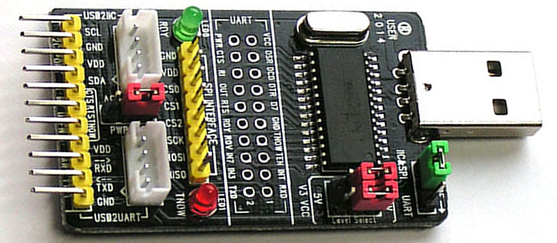
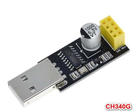
Here are the files you can find and what they contain ( the first two are the ones you need): The manufacturer provides a lot of useful things on the product page. Otherwise the device will be recognized as a standard USB to serial converter. That’s why you should put a jumper across pins 1 and 2 of the UART connector. Note that the device works as a programmer only if ACT# pin is connected to ground via a resistor. You will also need to connect V3 pin (9) to VCC (3.3V). In order to turn this programmer into a 3.3V device, you could cut the 5V line from VCC pin (28) and tie it to the 3.3V output from regulator. For improved reliability, I would recommend using a level shifter. They also forgot this one.Įven so, I used the device with I2C EEPROMS (3.3V and 5V) compatible and also SPI FLASH memories (3.3V devices) without any issues. I don’t know why the designer even used a regulator, if it didn’t provide a switch to choose 3.3V or 5V levels and supply.īy reading the datasheet, we can see that the manufacturer recommended to connect a 0.47uF capacitor between RSTI (pin 2) and VCC for improved stability. And this seems to be the only function of the 3.3V regulator (besides the 3.3V pin on the SPI connector). Basically this is a 5V device. The problem is that any memory you fit in the socket will be powered from 3.3V.

The chip is powered from 5V, so its I/O ports will also use 5V.

Now, let’s return to the schematic and analyze it a bit. Their product page offered a the PCB design of the device (only top side, however). Further searching lead me to WAVGAT store (on AliExpress).


 0 kommentar(er)
